Paintbrush
Project Purpose: Button module and dc motor using Pinoo Control Card To create a paint brush system with buttons.
Duration: 2 lessons
Age group: 7 years and older
Pinoo Set: Full Set.
Achievements:
Learn to code Pinoo control board
Learns to code the button module.
Dc motor learns to code.
Develops algorithmic skills.
Coding skills develop.
Materials to be used: Mblock 3 program, Pinoo Control Card, Button Module, Dc motor, Connection Cable.
Materials Required for Design: Forex, pad cotton, cylinder 3D printout, scissors, glue gun, paint, tape
Project Construction:
We divide the pad cottons into two separate parts and cover the perimeter of our cylinder in 2-3 layers with the help of a silicone gun.
We cut four rectangular pieces 3 cm wide from Forex.
We fix one of the parts to the engine with the help of a silicone gun. We fix another part to the engine.
We fix the third part, leaving the rod part of the motor on top.
We fix the motor cables to the inner part with tape.
We open a 2 x1 cm horizontal rectangular window in the middle of our last remaining rectangular piece. We stick the button module on the upper part of the rectangle and pass the cable through the window and take it inside.
We fix the part where we stick the button module to the idle part of the engine.
***Cables should be visible from the bottom section. If you wish, you can shorten the length of the pieces at this stage.
We close the upper part of the engine by cutting a piece of forex.
We cut two square pieces of 10.5 x 10.5 cm and two rectangular pieces of 10x4 cm from Forex. You can color the pieces at this stage if you wish.
We open a 2x2 cm square window in the middle of one of our square pieces.
We fix this square piece to the bottom of the design we created with the engine.
*** we let the motor and button cables pass through this window.
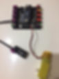
Let's make our connections. We connect the motor cable to the A1/A2 input (right) from the appropriate inputs for the motor, and the button module to the purple input number 4 with a connection cable.
We fix the other square piece to the bottom of our Pinoo board and the rectangular pieces to form a wall.
We attach the cylindrical part to the engine.
You can decorate the design as you wish.
We have completed our connections and design, now let's move on to the coding part. For this, use the mblock-3 application. we will use
Let's connect our Pinoo Control Card to the computer with the help of the connection cable and log in to the Mblock3 application. Then let's introduce our Pinoo Control Card to the computer. For this, we first click on the serial port option on the Connect tab. Then we select COM3. (The number may differ depending on the computer and the port.)
After making the serial port connection, let's choose the card we will use from the cards tab. We are working with the Nano model of Arduino.
In order to add the Pinoo extension to our computer, we click on the manage extensions option from the extensions tab. In the window that opens, we write “Pinoo” in the search engine and it is enough to say download to the result. It has been installed on our computer.
We come to the extensions tab again and click on Pinoo. We will write our codes with the Pinoo extension.
In the coding part; We get the code when we click on the Green Flag from the Events menu to start the application. Since we want all the code blocks we will write to work continuously, we start by taking the code block from the control tab to repeat it continuously. We will get help from the puppet to learn the value of the button module. For this, we get the command to say hello from the view tab. Instead of the hello phrase, we get the code block related to the button module in the robots tab. We change the pin input to Pinoo4, which we connect to.
Let's click on the green flag and observe the values that the sensor receives by pressing the button. If the value of the button is 1, that is, if the button is pressed, let the motor start, if not (if the value is 0), the motor should stop. Now let's turn this into code.
To create the Condition(If) loop, we get the if not statement from the control tab.
To create the condition section, we get the expression equal from the operations tab. In the first box, we place the code block related to the button module from the robots tab. We change the pin number to pinoo4. We write 1 in the second box.
If the button value is equal to 1, the motor, namely the brush, must rotate. For this, we get the Pinoo Bot Wheel: Right Direction Forward Speed 0 command from the robots tab. We change the speed part to 255.
If the button value is not 1, that is, if the button is not pressed, the motor/brush must be at rest. For the otherwise section, we get the Pinoo Bot Wheel: Right Direction Forward Speed 0 command from the robots tab.
After completing our codes, we check the operation of our project by clicking the green flag. When we press the button, our brush should be rotating. When we take our hand off the button, our brush should stop.
If there is no problem in the operation of our project, we need to load the codes we have written into our card in order to run our project with a power supply independent of the computer.
For this, we used the code to click on the green flag at the beginning and the code where we had the puppet tell the button value. by throwing it in the trash, we get the Pinoo Program code from the Robots menu.
Right click on the code and click upload to arduino. (We work with arduino as a board.)
We are waiting for the codes to be uploaded to the card. After the installation is complete, we close the window.
If there is no problem, we remove our power cable from the computer. We power our Pinoo Control card with the help of a 9v battery and a battery cap. We also bring the on-off button, which is right next to the battery input, to the on position.


.jpg)


.jpg)