Sweet Robot
Project Purpose: To make a cute robot project using Pinoo Control Card, servo motor, led module and distance sensor.
Duration: 2 lessons
Age group: 7 years and older
Pinoo Set: Basic set, invention set, maker set and full set.
Achievements:
Learns to code Pinoo control board.
Learns to use led module.
Learns to use distance sensor.
Learns to use servo motor.
Develops algorithmic skills.
Coding skills develop.
Materials to be used: Mblock 3 program, pinoo control card, distance sensor, yellow led module, red led module, servo motor
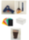
Materials Required for Design: 1 medium box, scissors and utility knife, colored cardboard, 4 cardboard cups, glue gun and silicone.
Project Construction:
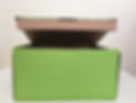
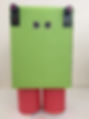
Let's start with the robot design for our project. We cut it from colored cardboard and cover the box with silicone so that the lid can be opened.
We cover all parts as in the figure. Thus, we complete the body of the robot design.
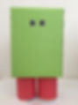
We put 2 cardboard cups together and silicone them. We do the same process one more time.
We cover the outside of 2 glasses with colored cardboard by silicone. Thus, we complete the legs of the robot design.
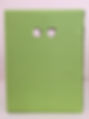
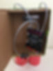
We drill holes in the upper part of the robot's body, where the distance sensor can enter.
We place the distance sensor in these holes and siliconize it.
We silicone the feet we created under the body part.
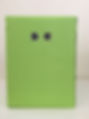
We siliconize 2 led modules at the level of the distance sensor.
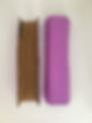
We cut cardboard to be 7x12 cm. Then we cut the top of it with colored cardboard and silicone it.
We bend it 2 cm from the right and left edges to the inside. Thus, we finish the arm part of the robot design.
We silicone one of the arms on the left side of the robot's body.
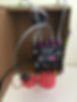
We remove the tip of the servo motor and silicon it on the body of the robot perpendicular to the right.
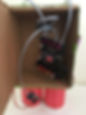
We attach the connection cables of the modules to the pinoo control card. We attach the distance sensor to the 5th Door, the red LED module to the 4th Door, the green led module to the 1st Door, and the servo motor to the 2nd Door.
We plug the USB connection cable into the Pinoo card and the computer. Now we can start coding.
Adding Pinoo extension:
From the Extensions tab, click "Manage Extensions".
In the window that opens, we write “Pinoo” in the search engine and it is enough to say download to the result. Installed on our computer.
Connecting the Pinoo control board to the computer:
In Mblock 3, we click on the "Connect" tab in the upper left. In the window that opens, we click on the "Serial Port" section and select the "COM6" option from the page that opens.
NOTE: As each computer has different port entries, the numbers next to COM may change.
Click on the Cards tab. From the window that opens, we select the "Arduino Nano" card option used by the Pinoo control card.
Click on the Extensions tab. In the window that opens, we select "Pinoo", the extension of the control card we use.
Click on the Connect tab. Click "Firmware Update" from the window that opens.
Coding part:
First, when the green flag is clicked, we make the angle of the servo motor 135 degrees.
We attach the tip of the servo motor vertically.
We silicone this arm parallel to the other arm to the end of the servo motor.
When the green flag is clicked, we constantly write the necessary codes to see the distance value to the 5th Gate on the screen. We see the value on the screen by clicking on the green flag and bringing our hand in front of the distance sensor. We use the red button to stop.
If not, we add the condition structure and create our condition. 5. We will have the condition that the value read by the distance sensor attached to the door should be less than 10. So if we put our hand close, it will work.
If our condition is true, we first make the red LED attached to the 4th door turn on by making its status high. 1. We make the yellow LED attached to the door turn off by lowering its status.
Then we add the code block by repeating 10 times from the control menu and change the value of 10 to 4.
In this part, we will change the angle of the servo motor and make it wave.
Repeat 4 times, we first make the angle of the servo motor 0 in the code block. We wait 0.5 seconds and make the angle of the servo motor 90. Then we wait 0.5 seconds again.
By advancing at these angles, we will get an image of waving.
If the condition is not true, we make the angle of the servo motor 135 degrees, which is the first value. Then, we make the yellow led attached to the 1st door turn on by making its status high. 4. We provide the status of the red led attached to the door, low leaf extinction.
Right-click on the “Pinoo Program” command and in the window that opens, “Install to Arduino” We select the option.
On the page that opens, we click on the "Upload to Arduino" button, which is selected in red.
Our codes are uploaded to our Pinoo control card.
After the “Installation Finished” message comes, click the “Close” button.
Working Status of the Project:
We insert the 9V battery.
When the robot does not detect any movement in front of it, it will stand still and the yellow LED will turn on.
When the robot detects a movement (you can put your hand in front of the distance sensor)
The red led will flash and the servo motor will start. This will make it look like the robot is waving.


.jpg)