zoetrope
Project Purpose: Button module and dc motor using Pinoo Control Card To create a Zoetrope system with
NOTE: Zoetrope is a system that displays still images as if they were in motion.
Duration: 2 lessons
Age group: 7 years and older
Pinoo Set: Full Set
Achievements:
Learn to code Pinoo control board
Learns to code the button module.
Dc motor learns to code.
Develops algorithmic skills.
Coding skills develop.
Materials to be used: Mblock 3 program, pinoo control card, button module, dc motor, connection cable
Materials Required for Design: Forex, cardboard, A4 paper, crayons, scissors, glue gun, tape, cardboard box, tongue stick
Project Construction:
We draw a circle with a radius of 7 cm and cut it.
We cut a 41 x 7.5 cm strip from A4 paper. One paper will not be enough for its length. That's why we connect two papers with tape. We draw shapes on the strip at certain intervals.
*** Figures must be suitable for consecutive zoetrope.
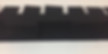
We cut a rectangle 41 x 18 cm wide from Black Cardboard.
We stick our strip in the middle of the black rectangle.
We will create rectangular gaps on the cardboard up to the top of our shapes. The important thing here is that the rectangular gaps we will cut coincide with the middle of the two shapes. (You can determine the gap dimensions based on your shapes)
We will do the same for the subsection this time. But this time, we make cuts between the shapes and fold the formed parts outwards.
We fix the two ends together to form a rectangular cylinder, with our strip coming to the inside.
We fix the cylinder we created on the circle with a silicone gun with the help of the parts we folded out. You can then cut off the excess parts.
We drill a hole in the middle part of the tongue bar.
From Forex we cut a rectangle the size of a tongue stick and two small rectangular pieces the size of the short side. We glue these small pieces on the short sides.
We fix the language bar to the design we created.
We fix the forex part of the design in the middle of the circle design we created.
We fix it by inserting the rod part of the motor into the hole we created on the tongue bar. (When the rod starts to rotate inside the hole, it should not be forced. At this stage, if the hole size is small, definitely expand it.)
First, we open a 3 x 1.5 cm window on the box, and then another window with the same dimensions in the lower part.
We fix the dc motor by taking the cable into the box to the upper window, and the button to the lower window by taking the cable into the box.
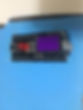
Let's make our connections. We place the Pinoo control card in the box. We connect the motor cable to the A1/A2 input (right) from the appropriate inputs for the motor, and the button module to the purple input number 4 with the connection cable. We close the box.
You can decorate the design as you wish.
We have completed our connections and design, now let's move on to the coding part. We will use the mblock-3 application for this. Let's connect our Pinoo Control Card to the computer with the help of the connection cable and log in to the Mblock3 application. Then let's introduce our Pinoo Control Card to the computer. For this, we first click on the serial port option on the Connect tab. Then we select COM3. (The number may differ depending on the computer and the port.)
After making the serial port connection, let's choose the card we will use from the cards tab. We are working with the Nano model of Arduino.
In order to add the Pinoo extension to our computer, we click on the Manage extensions option from the extensions tab. In the window that opens, we write “Pinoo” in the search engine and it is enough to say download to the result. Installed on our computer.
We come to the extensions tab again and click on Pinoo. We will write our codes with the Pinoo extension.
In the coding part; We get the code when we click on the Green Flag from the Events menu to start the application. Since we want all the code blocks we will write to work continuously, we start by taking the code block from the control tab to repeat it continuously. We will get help from the puppet to learn the value of the button module. For this, we get the command to say hello from the view tab. Instead of the hello phrase, we get the code block related to the button module in the robots tab. We change the pin input to Pinoo4, which we connect to.
Let's click on the green flag and observe the values that the sensor receives by pressing the button.
If the value of the button is 1, that is, if the button is pressed, let the motor start for 15 seconds, otherwise (if the value is 0) the motor stops. Now let's turn this into code. To create the Condition(If) loop, we get the if not statement from the control tab. To create the condition section, we get the expression equal from the operations tab. In the first box, we place the code block related to the button module from the robots tab. We change the pin number to pinoo4. We write 1 in the second box.
If the button value is equal to 1, the motor, namely the zoetrope, must rotate. For this, we get the Pinoo Bot Wheel: Right Direction Forward Speed 0 command from the robots tab. We change the speed section to 70. We want the motor/zoetrope to spin for 15 seconds after the button is pressed. We get the 1 second wait command from the control tab and change it to 15 for the phrase 1. If the button value is not 1, that is, the button is not pressed, the motor/zoetrope must be at rest. If not, we get the Pinoo Bot Wheel: Right Direction Forward Speed 0 command from the robots tab.
After completing our codes, we check the operation of our project by clicking the green flag. When we press the button, the zoetrope should be spinning for 15 seconds. If the button is not pressed zoetrope should stop.
If there is no problem in the operation of our project, we need to load the codes we have written into our card in order to run our project with a power supply independent of the computer. For this, we used the code to click on the green flag at the beginning and the code where we had the puppet tell the button value. by throwing it in the trash, we get the Pinoo Program code from the Robots menu.
Right click on the code and click upload to arduino. (We work with arduino as a board.)
We are waiting for the codes to be uploaded to the card. After the installation is complete, we close the window.
If there is no problem, we unplug our power cable from the computer. We power our Pinoo Control board with the help of 9v battery and battery cap. We also bring the on-off button, which is right next to the battery input, to the on position.


.jpg)